Created as a showcase project, AMAZE-28, the single-room summer house, was successfully constructed within 28 days on the grounds of the Kerala State Nirmithi Kendra. The 3D-printed building at the Kerala State Nirmithi Kendra in Thiruvananthapuram. (Photo: Shekunj) The inauguration of Kerala's inaugural 3D-printed structure, a 380-square-foot single-room summer house, is scheduled to take place on October 10 at the Kerala State Nirmithi Kendra (Kesnik) campus located in PTP Nagar, Thiruvananthapuram. Conceived as a showcase initiative, the summer house named AMAZE-28 was successfully finished within a mere 28 days. This impressive project was executed by Tvasta, a construction technology startup based in Chennai, founded by alumni of IIT-Madras, who have entered into a memorandum of understanding (MoU) with Kesnik. AMAZE-28 is perched upon a concrete foundation atop a gentle elevation within the Kesnik campus. Febi Varghese, the Director and Chief Executive Officer of...
If you're looking to get started with Arduino projects, controlling an LED using an Arduino board and a Python GUI is a great place to start. This project will not only help you understand the basic concept of controlling a device using an Arduino board, but it will also introduce you to the world of Python GUI programming. In this blog, we'll explore how to control an LED using an Arduino board and a Python GUI.
Arduino Projects and Python
Arduino is an open-source electronics platform that makes it easy for makers, hobbyists, and students to build interactive electronic projects. One of the simplest projects you can do with an Arduino board is controlling an LED. An LED is a small light-emitting diode that can be turned on and off using electrical signals. With an Arduino board, you can control the brightness and color of an LED using a few simple lines of code.
Python is a high-level programming language that's widely used in scientific computing, data analysis, and artificial intelligence. It's also a great language for GUI programming. With Python, you can create graphical user interfaces (GUIs) for your projects, making them easier to use and interact with.
In this Arduino projects, we'll use the Arduino board to control the LED, and we'll use a Python GUI to send signals to the Arduino board. The Arduino board will receive the signals from the Python GUI and control the LED accordingly.
Components Required
To get started, you'll need the following components:
| Name Components | Quantity |
| Arduino board | 1 |
| LED (5mm) | 1 |
| 220-ohm Resistor | 1 |
| Bread Board | 1 |
| Jumper Wires | As per need |
Circuit Diagram for this Arduino Projects
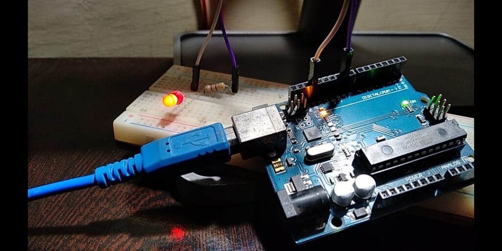
Once you have all the components, connect the LED to the Arduino board using the following circuit diagram:
Connect the positive leg of the LED to digital pin 9 of the Arduino board using a 220Ω resistor.
Connect the negative leg of the LED to the GND pin of the Arduino board.
Also Read: Python GUI and Arduino: Controlling LED using a Python based Graphics User Interface (GUI)
Codes for this Arduino Projects
Now, it's time to write the code for the Arduino board. The code for the Arduino board is simple and straightforward. You can use the following code to control the LED:
Arduino Code
void setup() {
  pinMode(9, OUTPUT);
  Serial.begin(9600);
}

void loop() {
  if (Serial.available() > 0) {
    int state = Serial.parseInt();
    digitalWrite(9, state);
  }
}
This code sets digital pin 9 as an output and initializes serial communication with the Python GUI. In the loop function, the code checks if any data has been received from the Python GUI. If data is received, it reads the integer value and sets the LED state to on (1) or off (0) accordingly.
Python GUI Code
Now, it's time to write the code for the Python GUI. You can use the following code to create the Python GUI:
import tkinter as tk
import serial

ser = serial.Serial('COM3', 9600)

def led_on():
    ser.write(b'1')

def led_off():
    ser.write(b'0')

root = tk.Tk()
root.title("LED Control")
root.geometry("200x100")

led_on_button = tk.Button(root, text="LED On", command=led_on)
led_off_button = tk.Button(root, text="LED Off", command=led_off)

led_on_button.pack()
led_off_button.pack()

root.mainloop()
This code creates a Python GUI with two buttons, "LED On" and "LED Off." The buttons are connected to the led_on and led_off functions, respectively. These functions use the serial library to communicate with the Arduino board and send signals to turn the LED on or off.

When the "LED On" button is clicked, the led_on function is called, and the serial library sends the value 1 to the Arduino board. The Arduino board receives the value and turns the LED on. When the "LED Off" button is clicked, the led_off function is called, and the serial library sends the value 0 to the Arduino board. The Arduino board receives the value and turns the LED off.


Conclusion
In conclusion, controlling an LED using an Arduino board and a Python GUI is a fun and educational project that can help you learn more about electronics and programming. It's also a great way to get started with Arduino projects and explore the capabilities of the Arduino board. With this project, you'll be able to control the brightness and color of an LED using a Python GUI, making your projects more interactive and user-friendly. So, why not try it out today and see what amazing projects you can build with an Arduino and Python!
Comments
Post a Comment