
Featured Post

Kerala's First 3D Printed Building

Created as a showcase project, AMAZE-28, the single-room summer house, was successfully constructed within 28 days on the grounds of the Kerala State Nirmithi Kendra. The 3D-printed building at the Kerala State Nirmithi Kendra in Thiruvananthapuram. (Photo: Shekunj)  The inauguration of Kerala's inaugural 3D-printed structure, a 380-square-foot single-room summer house, is scheduled to take place on October 10 at the Kerala State Nirmithi Kendra (Kesnik) campus located in PTP Nagar, Thiruvananthapuram.  Conceived as a showcase initiative, the summer house named AMAZE-28 was successfully finished within a mere 28 days. This impressive project was executed by Tvasta, a construction technology startup based in Chennai, founded by alumni of IIT-Madras, who have entered into a memorandum of understanding (MoU) with Kesnik.  AMAZE-28 is perched upon a concrete foundation atop a gentle elevation within the Kesnik campus. Febi Varghese, the Director and Chief Executive Officer of...

Python GUI and Arduino: Controlling LED using a Python based Graphics User Interface (GUI)

Python is popular language due to its simple syntax and user friendly properties. It is used in almost every domain form web development to scientific research and development applications. In this article python has been used to develop a simple GUI which used to control some hardware using a micro-controller. Video below shows the working of that GUI.


Components Needed

  1. Arduino UNO
  2. LED
  3. Breadboard
  4. Jumper wires
  5. Power supply
  6. Laptop with python installed

Schematic and Circuit

User have to command the controller using GUI. Controller will accept the command and  process it to give the out put. Schematic given below shows the process flow.

Figure given below shows the circuit diagram of this article. GUI is run on the computer screen and a serial communication connection between Arduino and Computer is established using USB. The command from GUI send to Arduino using this connection. A 5V DC power supply is used to power up the Arduino as well as LED. However it should be noted that, Arduino is connected to computer through USB so we do not need to supply the power to Arduino using some external source. If Arduino is not connected to computer then we need to power it up using some external source as shown in figure below.

LED +ve  terminal is connected to  digital PIN 8 of Arduino through a resistor (220 - 1000 ohm), while -ve terminal is connected to ground of power supply (GND). Next step is to discuss the GUI for controlling this LED.
 

GUI 

The GUI is developed using Tkinter module in python language.  Basically it contains three control buttons -

  1.  ON
  2.  OFF
  3. QUIT
ON button put the LED in ON mode, OFF button to put LED in OFF mode while QUIT button is to exit the OFF the LED and exit the GUI. The code for this GUI is given and discussed below. GUI also have one status bar, which shows the current status of the LED. Figure below shows the GUI and its different components.
 
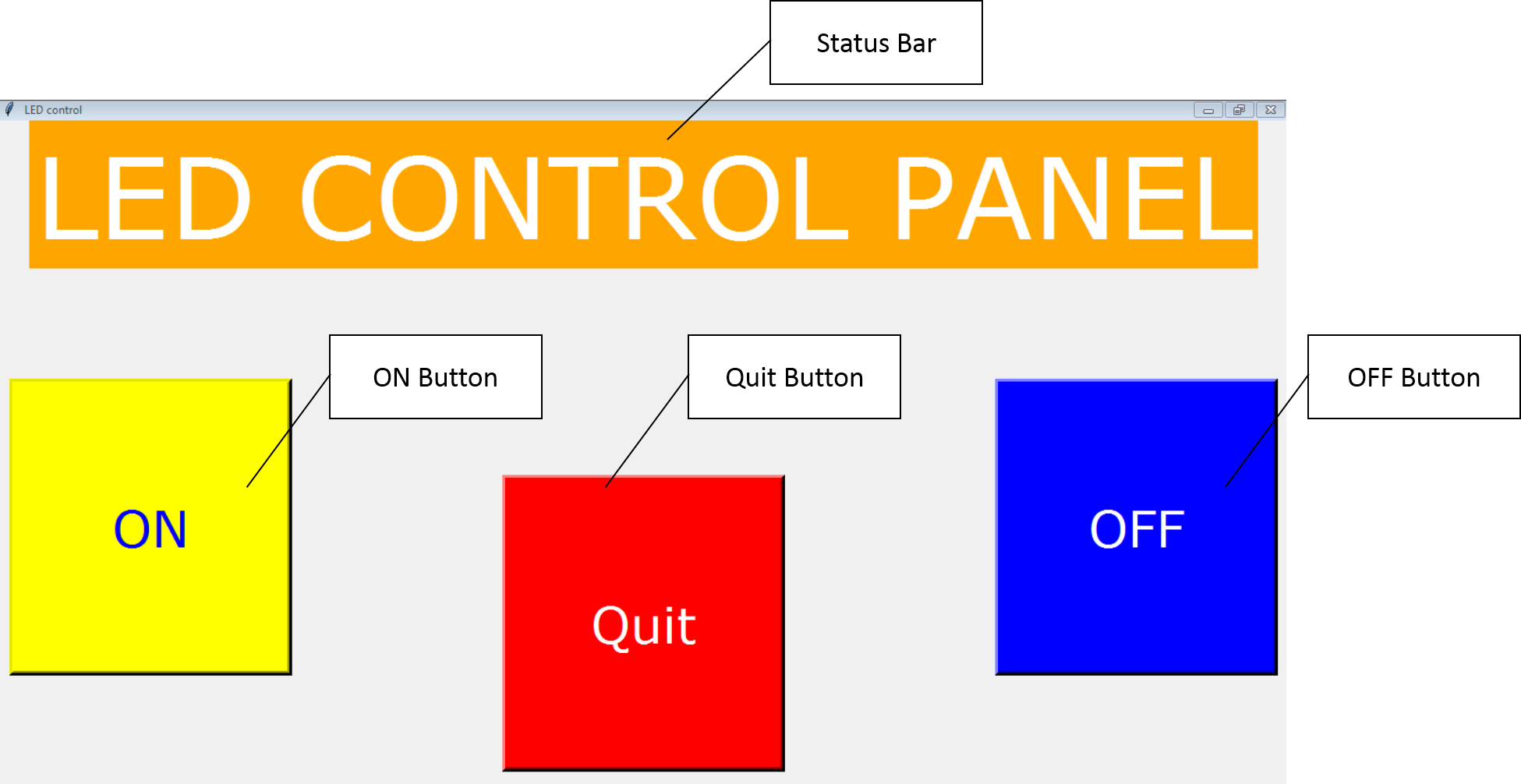
Main Window of Developed GUI with various buttons and status bar.


Showing Status of LED in status bar when LED is ON.

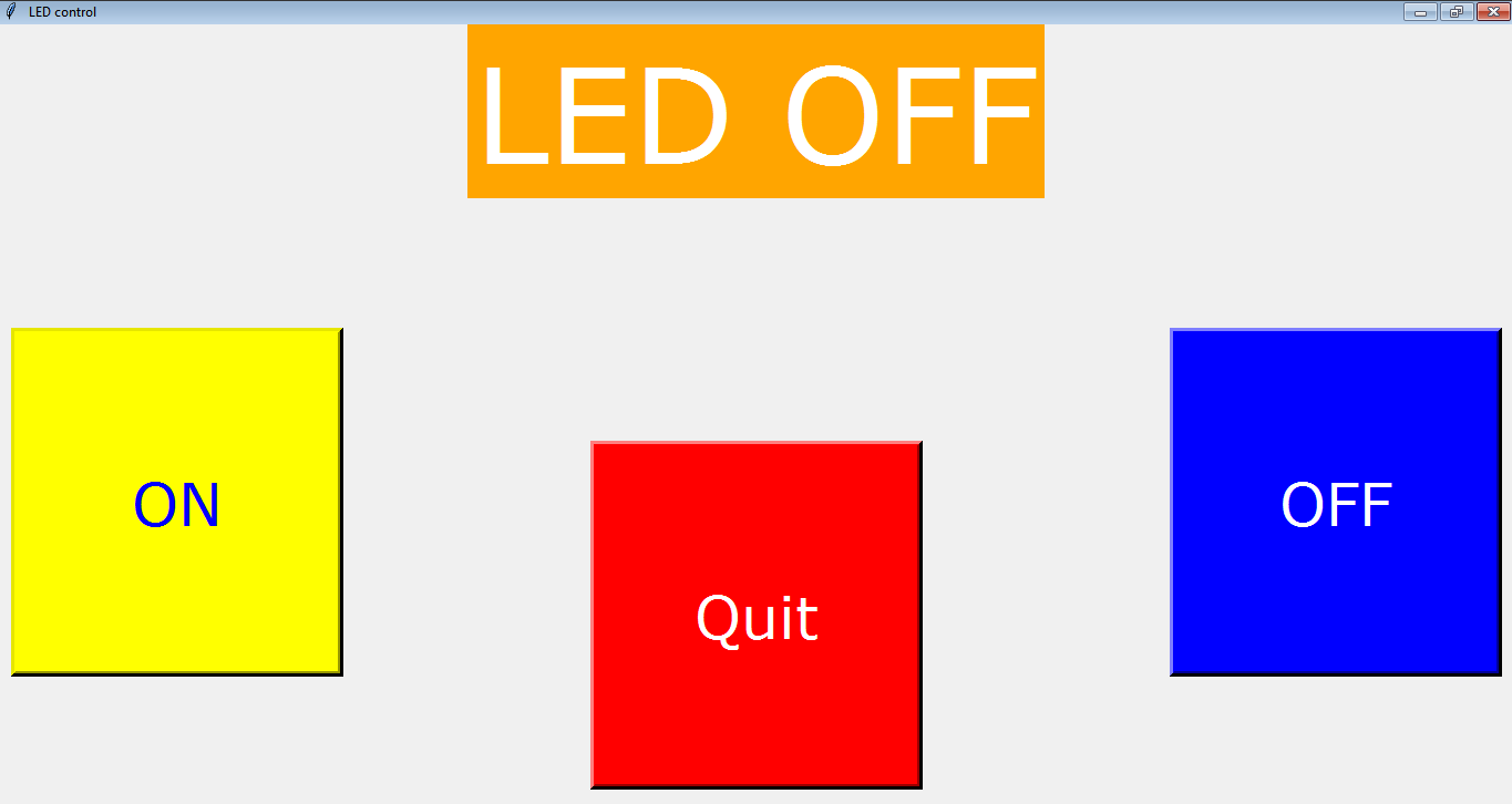
Showing Status of LED in status bar when LED is OFF.
 
Python code for the developed GUI is given below.

PYTHON CODE


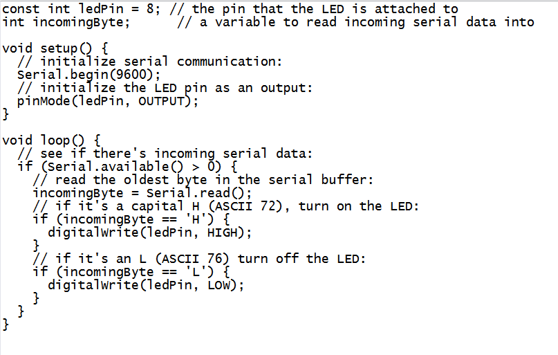
Now, let us discuss the Arduino Code.

Arduino Code

The Arduino code for this project is given below.
 

NOTE -    You will see little difference in the GUI shown in video and GUI discussed here. GUI discussed here, is the improved version while GUI shown in video is the initial version.

 Conclusion

The GUI for Controlling the LED has been successfully developed. We hope, it will help you to solve your problems by little modifications in the code and hardware. If you need code, please let us know in the comment section, we will email it you.


Comments

Popular posts from this blog

Making LED Fade in and out using Arduino

Hi Friends!!!!!! We have learnt how to blink LED with the help of Arduino, that's great! But now we will learn how to make a LED fade in and out gradually using a function in arduino : analogWrite(); Let's have a look on components, which we are going to need ahead. COMPONENT NEED -  Breadboard (1) Arduino (1) Jumper Wires LED 5mm (1) Resistor1K ohm (1) Power Source 5V (1) Now we place these components to make a proper circuit. CIRCUIT PREPRATION - Black wire - GND Red Wire   - +5V Take the breadboard and arduino. Connect the GND from arduino to -Ve terminal on breadboard. Similarly +5V to the +Ve terminal on breadboard.   Now place the LED on breadboard. Connect the positive terminal of LED to the 9th pin of arduino. Why we connecting the LED to the pin 9 of arduino ???? Because pin 9 of arduino can be used for PWM purpose. We needed PWM (Pulse Width Modulation) because Arduino board can only give digital signal (HI...

Controlling LEDs over WiFi using NodeMCU and Blynk App.

This article is the base on the Internet of things ( IoT ) . IoT describes the network of physical objects—“things” or objects—that are embedded with sensors, software, and other technologies for the purpose of connecting and exchanging data with other devices and systems over the Internet. In this article 3 LEDs will be controlled by an android application (made using Blynk) over a wifi connection. How to use NodeMCU with Blynk  If you want to start learn the Internet of Things (IoT) concept, then controlling a LED over the  internet is the " Hello World!" of the IoT journey. Performing the " Hello World" task will be easy using NodeMCU micro-controller as the first client and Blynk as the 'broker' or server and Blynk android application as the second client. Now communication between two clients will happen through broker over the internet. Now lets, make this happen.  Components Required For this activity we will need following components: Nod...

Blinking of LED Using Arduino UNO

Hi !!!! Here we are going to learn very very simple use of Arduino, that is blinking of a LED. Here we will do simplest project using Arduino. So, here we go.... COMPONENTS REQUIRED - Bread Board Arduino UNO Jumper Wires Power Source (5V) / Battery Resistor (1K) CIRCUIT PREPA RATION - Take bread board and Arduino. Connect the +5V from Arduino to the +Ve line on Bread Board and GROUND from Arduino to -Ve line on bread board. Red Wire     : +5 V Black Wire  : GROUND     Now put a LED on bread board. Connect the Anode (+ / Longer terminal) of led to the pin 13 of Arduino. Connect Cathode (- / Shorter terminal)  to 1K ohm resistor and connect another terminal of resistor to the GND on breadboard.   Now our circuit is ready to work.  Our next aim is to build the code. Let's make our code. CODE -     To download the complete code -  CLICK HERE -----------------------------...