Featured Post

Kerala's First 3D Printed Building

Created as a showcase project, AMAZE-28, the single-room summer house, was successfully constructed within 28 days on the grounds of the Kerala State Nirmithi Kendra. The 3D-printed building at the Kerala State Nirmithi Kendra in Thiruvananthapuram. (Photo: Shekunj)  The inauguration of Kerala's inaugural 3D-printed structure, a 380-square-foot single-room summer house, is scheduled to take place on October 10 at the Kerala State Nirmithi Kendra (Kesnik) campus located in PTP Nagar, Thiruvananthapuram.  Conceived as a showcase initiative, the summer house named AMAZE-28 was successfully finished within a mere 28 days. This impressive project was executed by Tvasta, a construction technology startup based in Chennai, founded by alumni of IIT-Madras, who have entered into a memorandum of understanding (MoU) with Kesnik.  AMAZE-28 is perched upon a concrete foundation atop a gentle elevation within the Kesnik campus. Febi Varghese, the Director and Chief Executive Officer of...

Micro-Python on NodeMCU ESP8266 (Windows guide)


This tutorial will guide you through setting up MicroPython on NodeMCU, getting a prompt, using WebREPL, connecting to the network and communicating with the Internet, using the hardware peripherals, and controlling some external components.

Requirements –

1.       NodeMCU Module
2.       Laptop with Python installed. (Here I am using python 2.7).
3.       Internet connection

Connecting the board to Power-

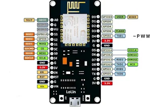
Connect the board to your laptop through USB to power it up. You can also give it external power supply at Vin pin (shown in fig. below). Please refer to the documentation for your board for further details.
Figure 1: NodeMCU Module

Firmware download –

Download the most recent MicroPython firmware .bin file to load onto your NodeMCU device. You can download it from here, and place it in your python/Scripts directory from earlier (screenshot).

Flashing the Firmware –

Before flashing the firmware I assume that you have python (2.7) with pip tool.
So, follow the following steps –
·         cd /
·         cd Python27 (or whatever directory you installed it to)
·         cd Scripts
·         pip install esptool
esptool – it is a Python-based, open source, platform independent, utility to communicate with the ROM bootloader in Espressif ESP8266.


  • Plug your USB cable into the NodeMCU board, and then into your computer.
  • Go into device manager and confirm what port your device is on. We'll need this information later. I'm on COM port 3 (screenshot).
  • Place the NodeMCU board into bootloader mode by holding the flash button, pressing the RST button, then releasing the flash button. You'll see the blue light briefly flash once when you've done this (screenshot).
  • Open a command prompt, and return to the scripts directory.
  • Run the following command, keeping in mind to substitute COM3 with YOUR particular COM port:
esptool.py --port COM3 --baud 460800 write_flash --flash_size=detect 0 esp8266-20161110-v1.10.bin
Congratulations!!!! You've successfully flashed Micropython onto a microcontroller!
Connect Using TeraTerm + WebREPL - (coming soon...)


Comments

Popular posts from this blog

How to Know the NodeMCU IP Address for Your Next IoT Project

  NodeMCU IP Address: The NodeMCU is a popular development board for IoT projects. It’s small, affordable, and comes with built-in Wi-Fi connectivity, making it the perfect choice for creating connected devices. But before you can start building your NodeMCU projects, you need to know the IP address of your device. This IP address is essential for communicating with the NodeMCU from another device, such as a computer or smartphone. In this article, we’ll show you how to find the NodeMCU IP address, so you can get started with your next IoT project. Method 1: To Know the NodeMCU IP Address One of the easiest ways to find the NodeMCU IP address is by using the serial monitor in the Arduino IDE. First, connect your NodeMCU board to your computer using a micro-USB cable. Then, upload the following code to the NodeMCU: #include <ESP8266WiFi.h> void setup() { Serial.begin(115200); Serial.println(); Serial.print("Connecting to "); Serial.println(...

Making LED Fade in and out using Arduino

Hi Friends!!!!!! We have learnt how to blink LED with the help of Arduino, that's great! But now we will learn how to make a LED fade in and out gradually using a function in arduino : analogWrite(); Let's have a look on components, which we are going to need ahead. COMPONENT NEED -  Breadboard (1) Arduino (1) Jumper Wires LED 5mm (1) Resistor1K ohm (1) Power Source 5V (1) Now we place these components to make a proper circuit. CIRCUIT PREPRATION - Black wire - GND Red Wire   - +5V Take the breadboard and arduino. Connect the GND from arduino to -Ve terminal on breadboard. Similarly +5V to the +Ve terminal on breadboard.   Now place the LED on breadboard. Connect the positive terminal of LED to the 9th pin of arduino. Why we connecting the LED to the pin 9 of arduino ???? Because pin 9 of arduino can be used for PWM purpose. We needed PWM (Pulse Width Modulation) because Arduino board can only give digital signal (HI...

Python GUI and Arduino: Controlling LED using a Python based Graphics User Interface (GUI)

Python is popular language due to its simple syntax and user friendly properties. It is used in almost every domain form web development to scientific research and development applications. In this article python has been used to develop a simple GUI which used to control some hardware using a micro-controller. Video below shows the working of that GUI.   Components Needed Arduino UNO LED Breadboard Jumper wires Power supply Laptop with python installed Schematic and Circuit User have to command the controller using GUI. Controller will accept the command and  process it to give the out put. Schematic given below shows the process flow. Figure given below shows the circuit diagram of this article. GUI is run on the computer screen and a serial communication connection between Arduino and Computer is established using USB. The command from GUI send to Arduino using this connection. A 5V DC power supply is used to power up the Arduino as well as LED. However it should be noted t...