
Featured Post

Kerala's First 3D Printed Building

Created as a showcase project, AMAZE-28, the single-room summer house, was successfully constructed within 28 days on the grounds of the Kerala State Nirmithi Kendra. The 3D-printed building at the Kerala State Nirmithi Kendra in Thiruvananthapuram. (Photo: Shekunj)  The inauguration of Kerala's inaugural 3D-printed structure, a 380-square-foot single-room summer house, is scheduled to take place on October 10 at the Kerala State Nirmithi Kendra (Kesnik) campus located in PTP Nagar, Thiruvananthapuram.  Conceived as a showcase initiative, the summer house named AMAZE-28 was successfully finished within a mere 28 days. This impressive project was executed by Tvasta, a construction technology startup based in Chennai, founded by alumni of IIT-Madras, who have entered into a memorandum of understanding (MoU) with Kesnik.  AMAZE-28 is perched upon a concrete foundation atop a gentle elevation within the Kesnik campus. Febi Varghese, the Director and Chief Executive Officer of...

Seven Segment LED Display With Arduino : Part - I

Hi!!!
In this tutorial, we are going to learn how to use a seven segment LED display with Arduino. We will learn to interface seven segment display with Arduino and how to start and glow LEDs in a sequence. So, let's start -


COMPONENTS REQUIRED -  

  1. Arduino UNO (1)
  2. Breadboard (1)
  3. Jumper Wires
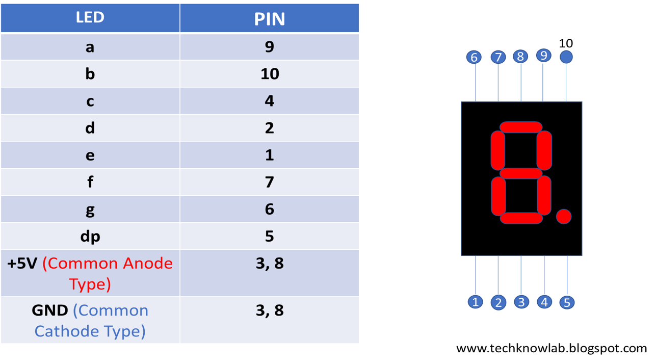
  4. Seven Segment LED Display (1) [Here we are using Common Anode Display]
  5. Resistor 220 Ohm (2)
  6. 5V Power supply
Components used in this tutorial.


Lets see some details about Seven Segment LED display - 
 Seven Segment display is an electronic device which is generally used to display 0 - 9 decimal numbers. It has seven segment made up of LEDs and one LED as decimal point. These displays are of two types -
1 - Common Anode type
2 - Common Cathode type


CIRCUIT -


Circuit diagram or connections.


CODE - 

In this section we will discuss about the code for  glowing all the segments (LEDs) in a sequence and putting them off in the same sequence.

To download full code CLICK HERE

 Lets have a look on code -


In this section of code, we just output pin for the arduino, with which each segment ( LED) is connected. Here segment "a to g" is connected with "2nd to 8th" pin of arduino respectively. Decimal point LED is left disconnected.


This is section of code which is repeated continuously. Since we have seven LEDs, so here we used 'for loop'. For loop will count from 2 to 8 ( <9 ). And arduino pin corresponding to number in for loop will be put HIGH. And after a delay of 0.6 second same pin will be put LOW. 


RESULT -

Here we completed our task. We can see that all the seven segments getting on and off in a sequence.
 

Comments

Popular posts from this blog

Making LED Fade in and out using Arduino

Hi Friends!!!!!! We have learnt how to blink LED with the help of Arduino, that's great! But now we will learn how to make a LED fade in and out gradually using a function in arduino : analogWrite(); Let's have a look on components, which we are going to need ahead. COMPONENT NEED -  Breadboard (1) Arduino (1) Jumper Wires LED 5mm (1) Resistor1K ohm (1) Power Source 5V (1) Now we place these components to make a proper circuit. CIRCUIT PREPRATION - Black wire - GND Red Wire   - +5V Take the breadboard and arduino. Connect the GND from arduino to -Ve terminal on breadboard. Similarly +5V to the +Ve terminal on breadboard.   Now place the LED on breadboard. Connect the positive terminal of LED to the 9th pin of arduino. Why we connecting the LED to the pin 9 of arduino ???? Because pin 9 of arduino can be used for PWM purpose. We needed PWM (Pulse Width Modulation) because Arduino board can only give digital signal (HI...

Controlling LEDs over WiFi using NodeMCU and Blynk App.

This article is the base on the Internet of things ( IoT ) . IoT describes the network of physical objects—“things” or objects—that are embedded with sensors, software, and other technologies for the purpose of connecting and exchanging data with other devices and systems over the Internet. In this article 3 LEDs will be controlled by an android application (made using Blynk) over a wifi connection. How to use NodeMCU with Blynk  If you want to start learn the Internet of Things (IoT) concept, then controlling a LED over the  internet is the " Hello World!" of the IoT journey. Performing the " Hello World" task will be easy using NodeMCU micro-controller as the first client and Blynk as the 'broker' or server and Blynk android application as the second client. Now communication between two clients will happen through broker over the internet. Now lets, make this happen.  Components Required For this activity we will need following components: Nod...

Blinking of LED Using Arduino UNO

Hi !!!! Here we are going to learn very very simple use of Arduino, that is blinking of a LED. Here we will do simplest project using Arduino. So, here we go.... COMPONENTS REQUIRED - Bread Board Arduino UNO Jumper Wires Power Source (5V) / Battery Resistor (1K) CIRCUIT PREPA RATION - Take bread board and Arduino. Connect the +5V from Arduino to the +Ve line on Bread Board and GROUND from Arduino to -Ve line on bread board. Red Wire     : +5 V Black Wire  : GROUND     Now put a LED on bread board. Connect the Anode (+ / Longer terminal) of led to the pin 13 of Arduino. Connect Cathode (- / Shorter terminal)  to 1K ohm resistor and connect another terminal of resistor to the GND on breadboard.   Now our circuit is ready to work.  Our next aim is to build the code. Let's make our code. CODE -     To download the complete code -  CLICK HERE -----------------------------...